Blueprint
On this pageSource sheetsFirst extractionDimensional auditPlan fidelityRepair decision
01The input

Two photographs contain the available architectural record.

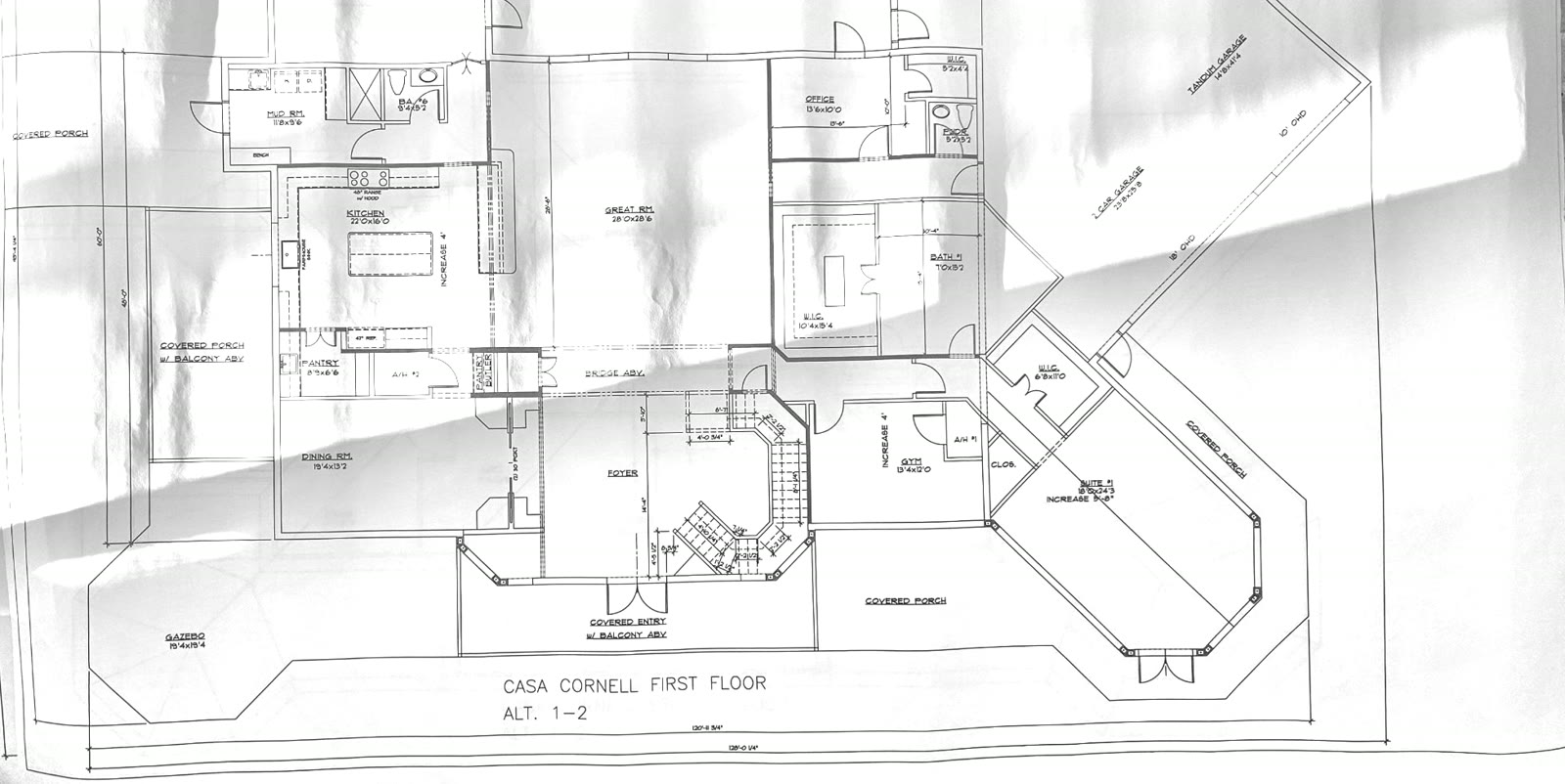
Both photographs carry camera EXIF dated 6 March 2026: paper drawings shot at an angle under window light, with a cast shadow across one corner. No CAD, survey or DWG accompanies them.
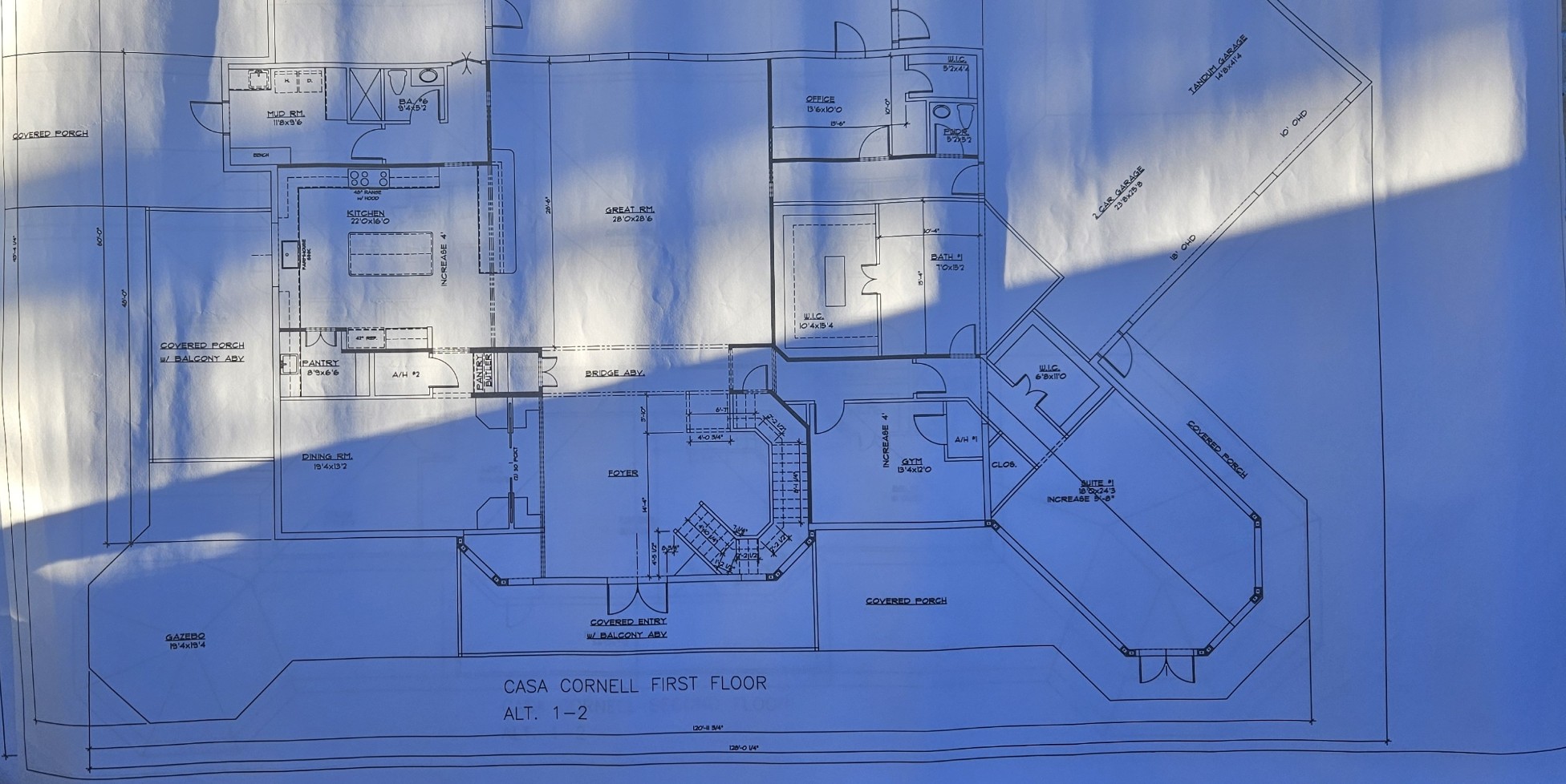
First floor plan as photographed
Source1952 × 978

First floor

28 named spaces. Blue cast from the window, cast shadow at the lower left.
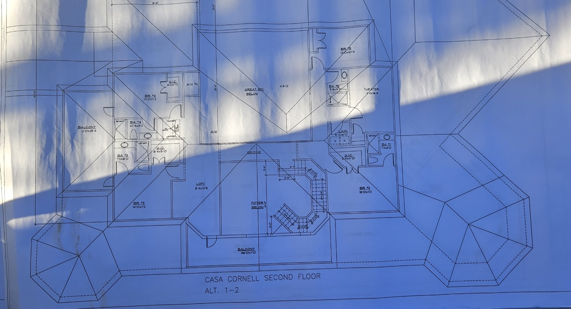
Second floor plan as photographed
Source1883 × 1018

Second floor

23 named spaces. Sharper sheet, heavier paper wrinkle through the middle.

01bCleanup

Cleanup isolates the drawn linework.

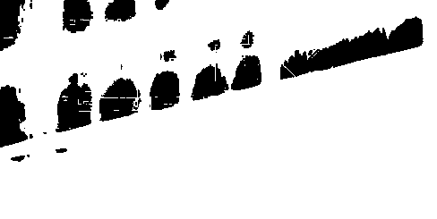
Black-hat morphology cleared the cast shadow and retained the paper wrinkle. RGB consensus separated printed ink from the blue window light and most paper texture while preserving small dimension marks. The RGB consensus output became the working plan image.

The rejected black-hat PNG weighs 3,117,022 bytes. The selected consensus PNG weighs 349,719 bytes and carries substantially less paper texture.
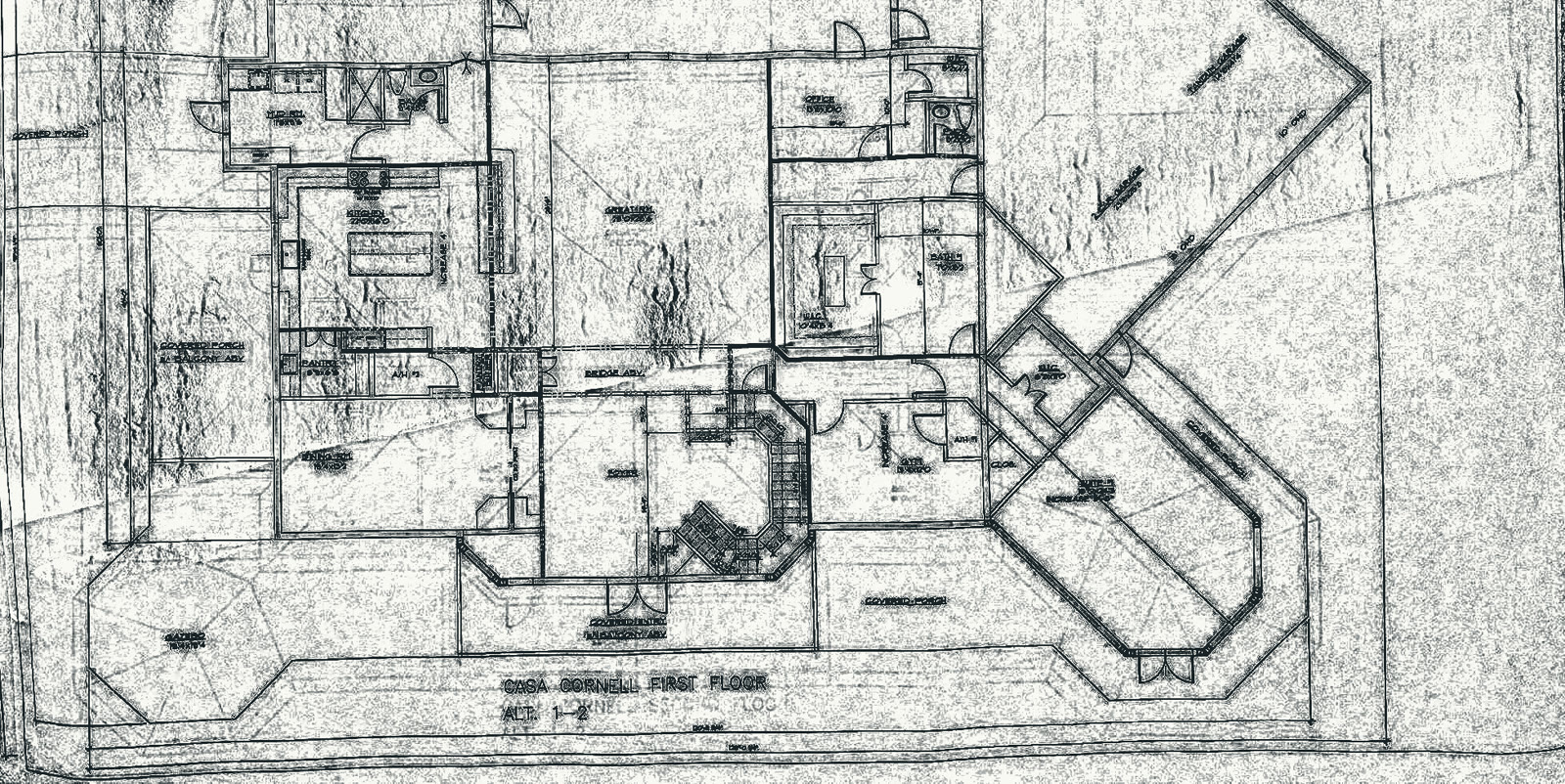
Black-hat cleanup result
Rejected

Black-hat morphology

The cast shadow cleared, while the paper wrinkle and surface texture remained.
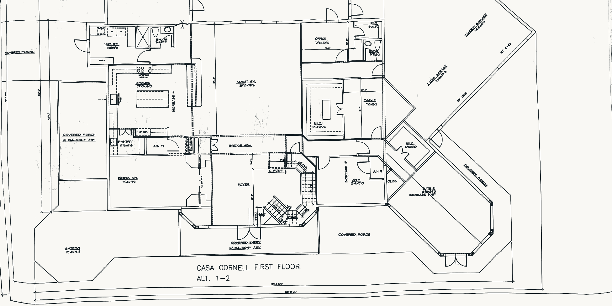
RGB consensus cleanup result
Selected

RGB consensus

Ink coverage 25.6% down to 7.3% on floor one, 22.8% to 7.7% on floor two.
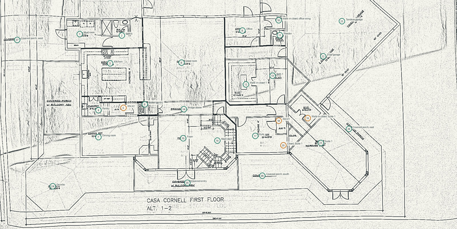
Evidence overlay audit
Audit

Removal overlay

Each removed pixel is painted over the source photograph for direct inspection.

Optical-density threshold sweep: at 0.14 the pass began attenuating low-contrast one-pixel dimension ticks and dashed construction lines, so 0.10 was selected. Neutral-ink boost was measured and disabled at 0.0; the operation only increased ink coverage.
02The first tries

The first extraction confused walls with everything else on the sheet.

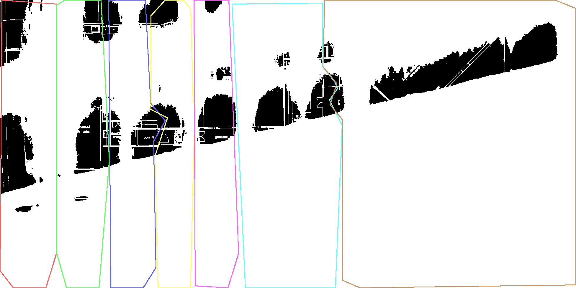
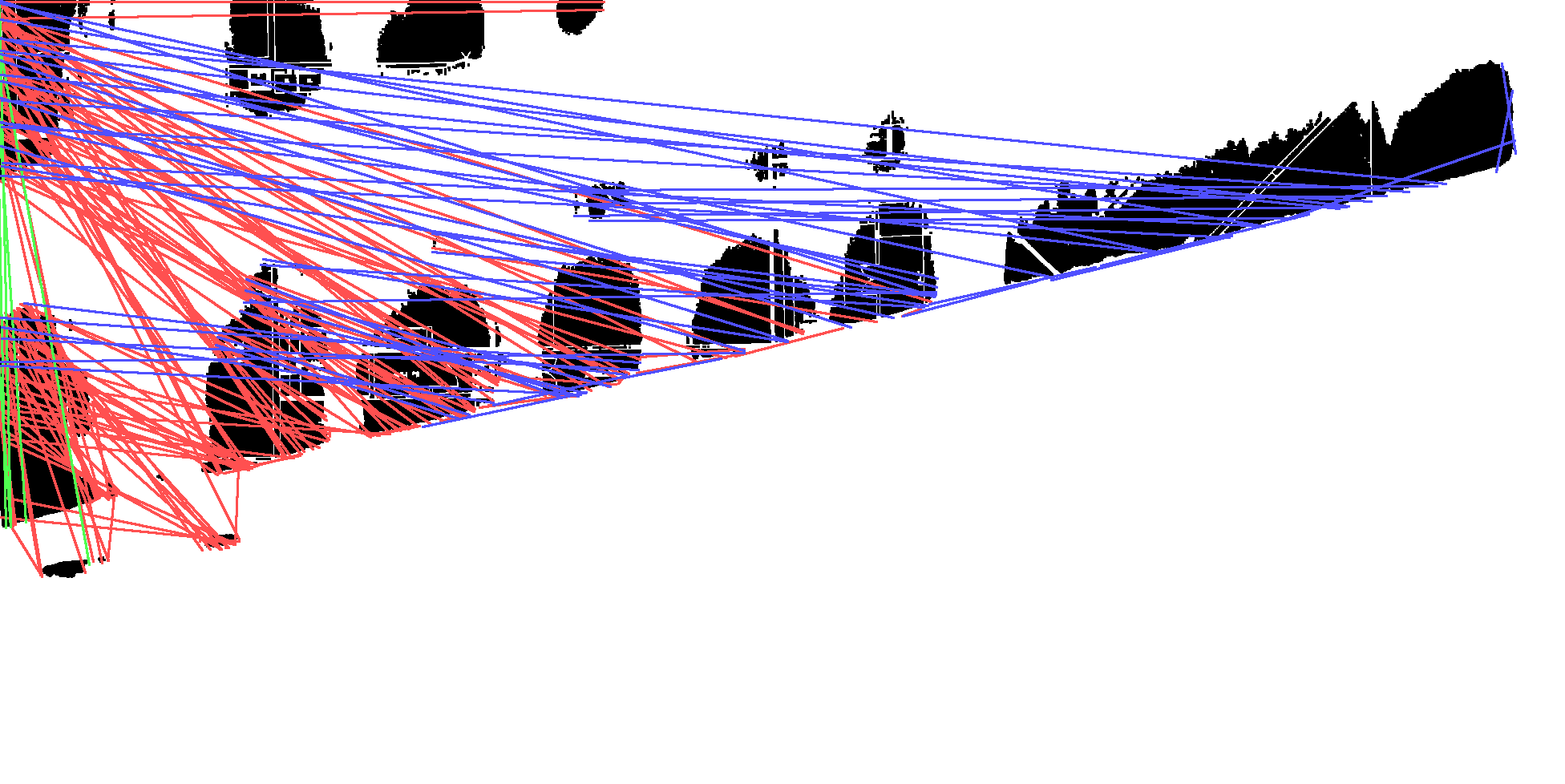
A local rule-based pass ran flat-field correction, a Hough transform, max pooling, closed-loop room segmentation and extrusion. Flat-field correction helped. Shared thresholds grouped walls with hatching, dimension ticks, the sheet border and door openings, so the SVG and extrusion preserve those errors.

The next extraction requires line semantics, opening-aware topology, printed-label association and an independent check against the dimension strings. This geometry remains rejected evidence.

Flat-field corrected plan
Stage 3

Flat-field

The illumination gradient was removed successfully. This operation remains part of the cleanup pipeline.

Hough line detection output
Rejected

Hough lines

With the settings used here, wall strokes, hatching, dimension ticks and the sheet border all enter the same line set.

Max-pooled wall grid
Rejected

Wall grid

The chosen max-pool radius connected broken wall strokes, but also closed the door openings.

Automatic room segmentation
Rejected

Auto room split

Every closed loop became a room candidate, including loops produced by the earlier threshold errors.

Early 3D extrusion
Rejected

First extrusion

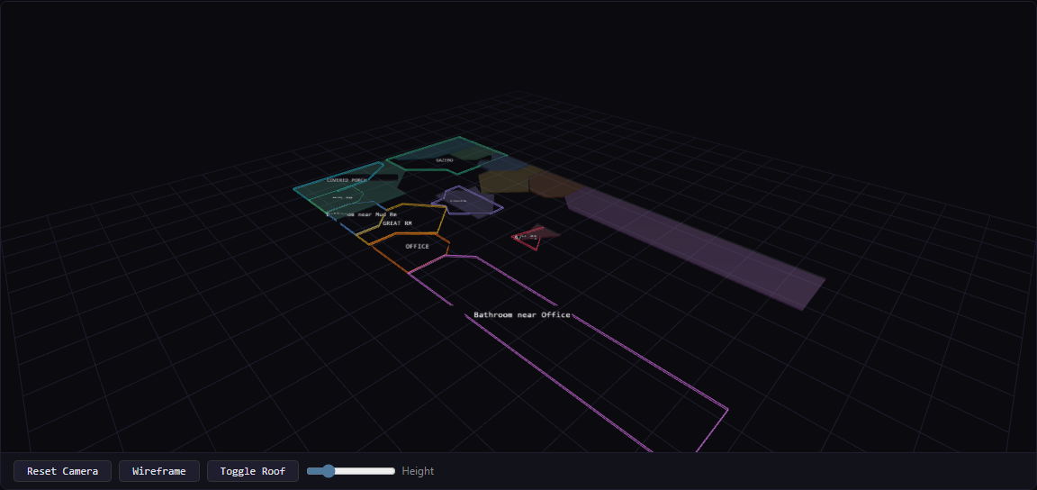
The extrusion carries the threshold and segmentation errors from the preceding stages into three dimensions.

How the evidence is separated

Room labels and geometry claims are stored separately. Labels are transcribed from the sheet; polygons are checked against surviving ink and the written dimensions. A segmentation score by itself is not enough to treat a polygon as architectural geometry.

03Reviewed geometry

Room names, measurements and traced polygons each get their own review.

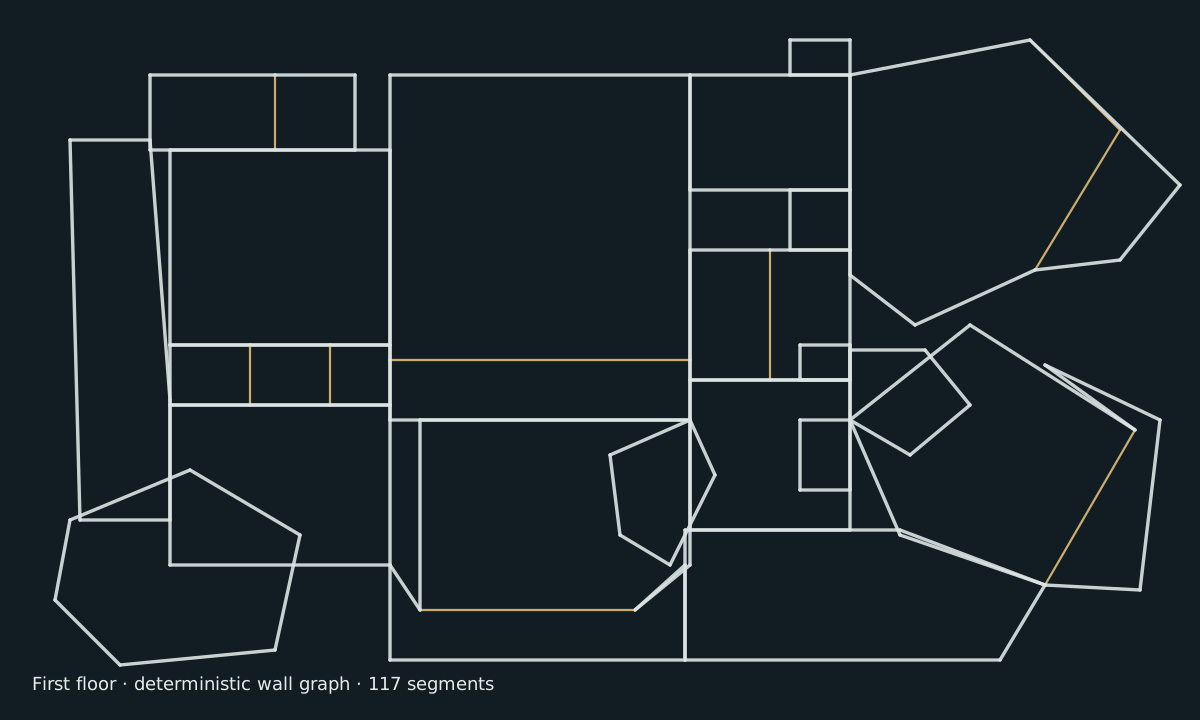
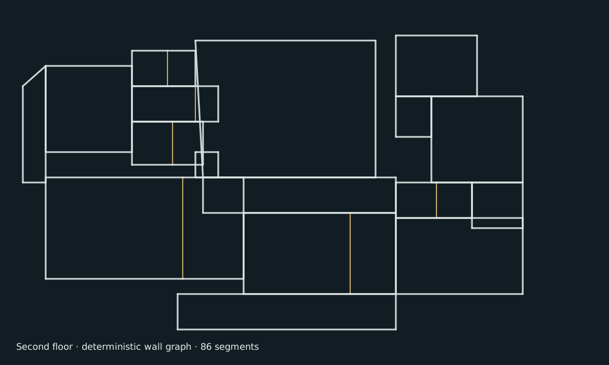
The reviewed schema carries 51 named spaces across 2 floors with 19 doors and openings. A separate room-perimeter graph carries 203 edges, 117 on the first floor and 86 on the second, the boundaries of the reviewed room polygons, each one naming the space or spaces it bounds.

The sealed artifact keeps the filename wall-graph.json. Its process manifest classifies it as rejected analysis evidence. These 203 edges describe room boundaries without thickness or centerlines; a partition between two rooms appears once with a shared flag.

Only 3 polygons passed the geometry review. Room names and dimensions do not validate polygon placement, so the project records those claims separately.

First floor plan with the two accepted traces drawn on it
PromotedSource pixel space

Kitchen and Great room

The traces retain the photograph’s pixel coordinates and original perspective.

Second floor plan with the accepted theater trace drawn on it
PromotedSource pixel space

Theater

Every other draft polygon behaved like a bounding box or crossed a source wall under independent review. Those candidates remain analysis evidence outside the promoted geometry set.

Acceptance threshold: 75% of edge samples within uncertainty plus 2 px of preserved source linework. Kitchen and Great room overlap by 0 px². Linked artifacts: wall-graph.json, floor-01-wall-graph.svg, floor-02-wall-graph.svg, verified-schema.json, accepted-traces.json, accepted-traces-validation.json. Displayed counts are sourced from these files.

03bVisual sequence

Follow the plan into the current spatial build.

The front-page sequence uses the preserved plan photograph, measured retrace, registered massing, camera-matched line control, final styled view, held-out reconstruction and playable Great Room.

03cAgainst the paper

The dimensional audit rejected the first geometry.

The lettered room dimensions provide an independent measurement for every polygon feeding the massing, camera paths and reconstruction studies.

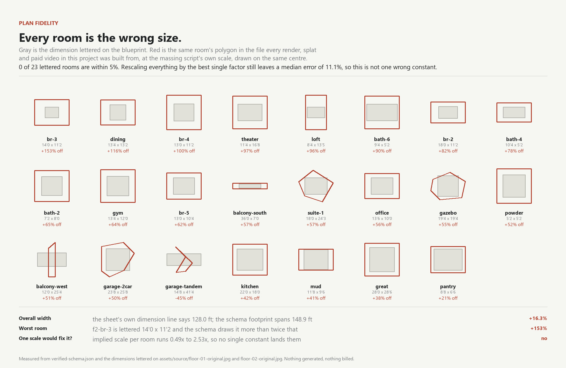
Each lettered dimension was read off the two source photographs and held against the minimum-area rectangle of that room’s polygon, converted through the massing script’s own scale constant. 0 of 23 rooms land within 5%. 23 are worse than 10%. The median room is out by 59.5%. The sheet’s own dimension line reads 128.0 ft across; the schema footprint spans 148.9.

Dimension transcription audit

The 23 transcribed strings were checked again at 6–10× zoom. Three entries were corrected: KITCHEN is 22’0″×16’0″; its depth had been entered as 18’0″. DINING RM is 19’4″ wide; it had been entered as 13’4″. PANTRY is 8’9″; it had been entered as 8’8″. The remaining 20 entries were confirmed. The corrected audit retained the same result: 0 of 23 rooms within 5%.

Twenty-three tiles, one per room. In
    each, a gray rectangle at the size lettered on the blueprint and a red outline of the same room's polygon
    from the reconstruction, drawn on the same center. The red outline is larger than the gray rectangle in
    every tile but one, by between 21 and 153 percent.
Gray shows the size lettered on the blueprint. Red shows the corresponding polygon used by the downstream renders, splats and video studies. Read from plan-fidelity.json.

A single scale correction was tested first. The implied room scales span 0.49× to 2.53× across rooms. Rescaling everything by the best single factor leaves a median absolute error of 11.9% and lands 12 of 46 room sides within 5%. Splitting by sheet gives the same picture: floor one spreads 0.69–1.90× and floor two 0.49–2.53×. Inside single rooms the two sides often disagree: in 11 of the 23 they imply scales more than 10% apart, and in 5 more than 25% apart. The west balcony comes out at 0.49× along one side and 1.19× along the other. These within-room disagreements show shape errors that a global scale correction cannot resolve.

The finding invalidated the building-scale claims derived from this schema. The 47.9 m frontage, opening-schedule wall lengths, fitted orbit radii and eight dependent splats all describe geometry that differs from the paper plan. The relative experiment results stay useful wherever they compare runs built on the same geometry: registration rates, held-out PSNR, chaining, alpha semantics, the comparison checks and recorded cost. They describe the experiment, and they stop short of the property at metric scale.

This local audit cost $0.00, and it reroutes a funded pipeline: new geometry must pass the same dimensional check before it can drive cameras or paid generation.

03dRepair or retrace

Transform fitting required a measured retrace.

The audit left two suspects: a consistent page transform, which a global correction could undo, or room-by-room tracing errors, which demand a retrace because sliding one room through a global transform drags its neighbors along.

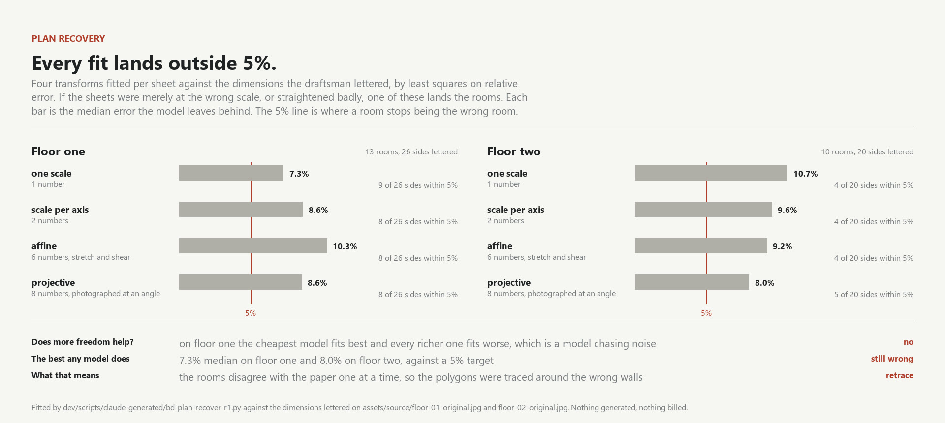
Four models were fitted per sheet against the dimensions the draftsman lettered, by least squares on relative error, each measured with the same minimum-area rectangle the section above used: one scale, one scale per axis, affine and projective. Their degrees of freedom are 1, 2, 6 and 8. The projective model represents perspective distortion from photographing a flat page.

Two panels, one per floor. Each has four
    bars, one per transform model, showing the median error left behind: on floor one 7.3, 8.6, 10.3 and 8.6
    percent as the models get richer; on floor two 10.7, 9.6, 9.2 and 8.0. A red line marks 5 percent and every
    bar runs past it.
Median absolute error left behind by each model, per sheet. The red line is 5%. Read from plan-recover.json.

On floor one the single-scale model fits best. One scale leaves a median of 7.3%; a scale per axis takes it to 8.6%, adding stretch and shear to 10.3%, and the projective fit comes back to 8.6%. Every extra degree of freedom fits floor one worse, indicating that no consistent page distortion can be recovered. Floor two improves with freedom and still stops at 8.0%. Across all eight fits, the most sides any of them lands inside 5% is 9 of 26 on floor one and 5 of 20 on floor two.

The errors vary room by room, so every fitted page transform misses the 5% tolerance, and the lettered dimensions become the basis for a fresh retrace. The House chapter follows that retrace into the massing, elevations, opening schedule, camera paths and reconstruction experiments.

All eight fits ran locally at $0.00. The failed tolerance check ended this geometry path before it could cost anything downstream.

BackOverviewNextCreate

Prepare a spatial reconstruction.