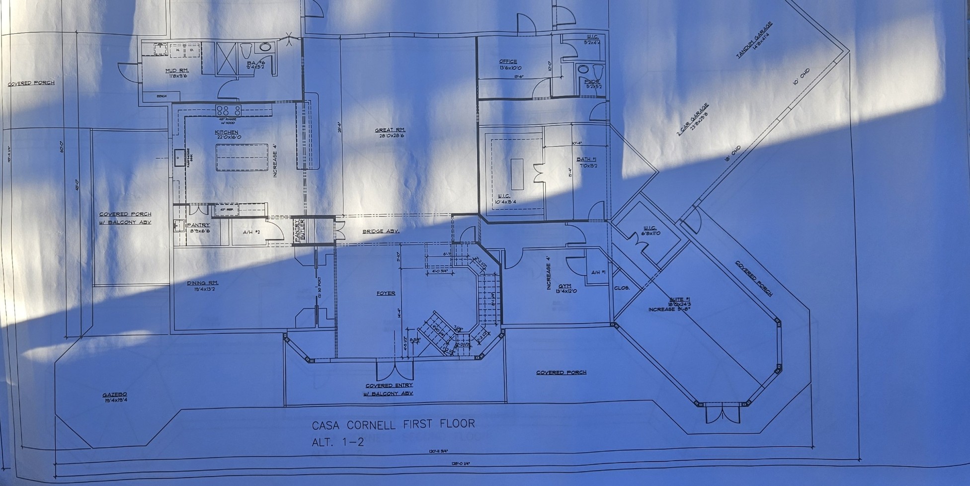
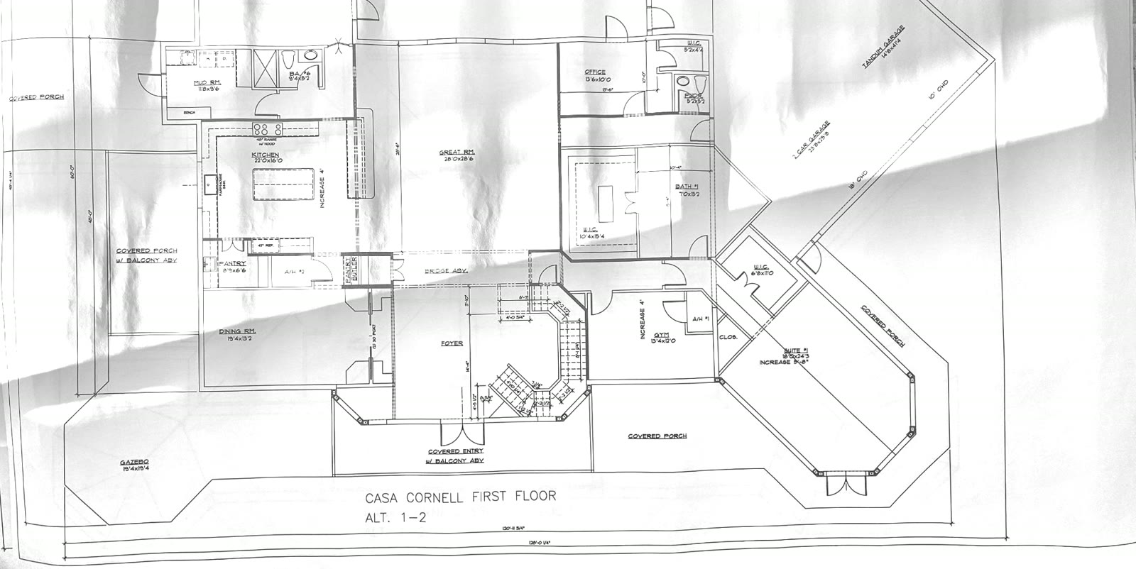
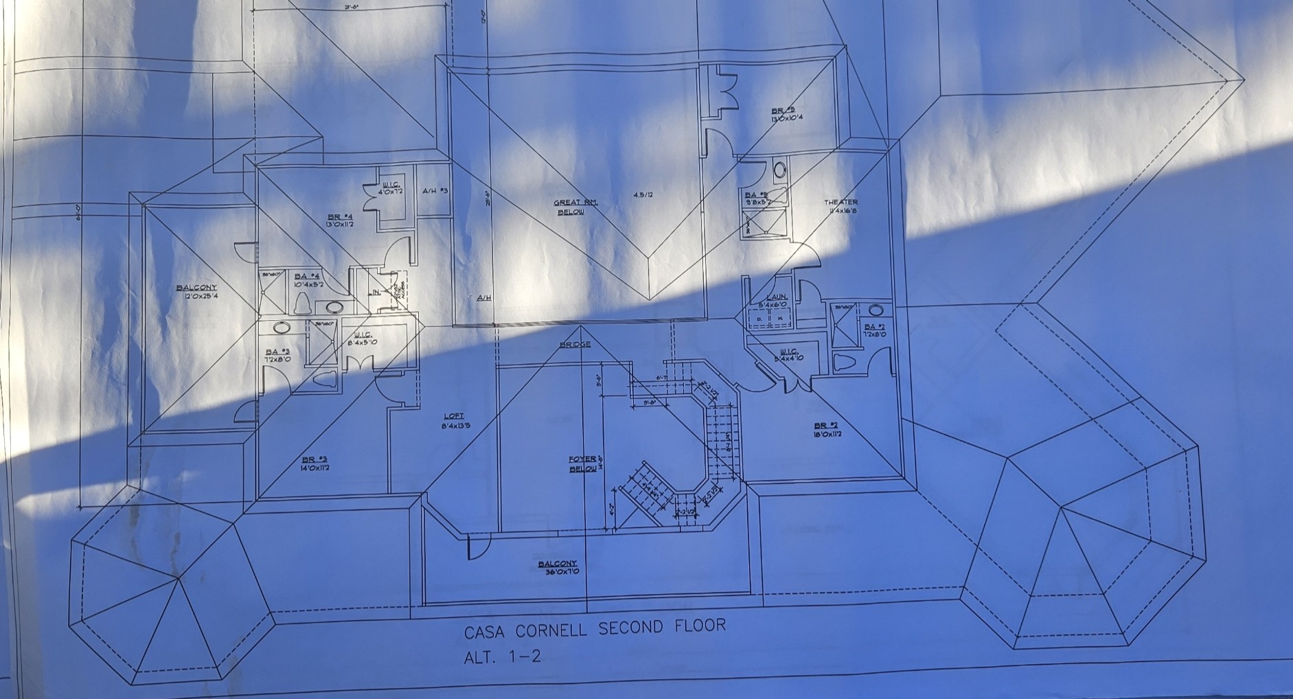
Both carry camera EXIF dated 6 March 2026. There is no CAD file, no survey and no DWG. Everything below is recovered from paper photographed at an angle, under a window, with a shadow over one corner.
28 named spaces. Blue cast from the window, cast shadow at the lower left.
23 named spaces. Sharper sheet, heavier paper wrinkle through the middle.
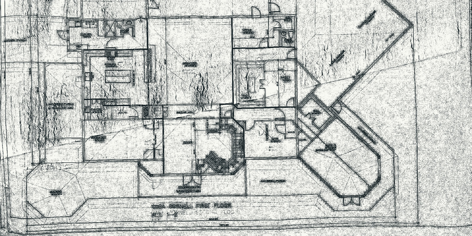
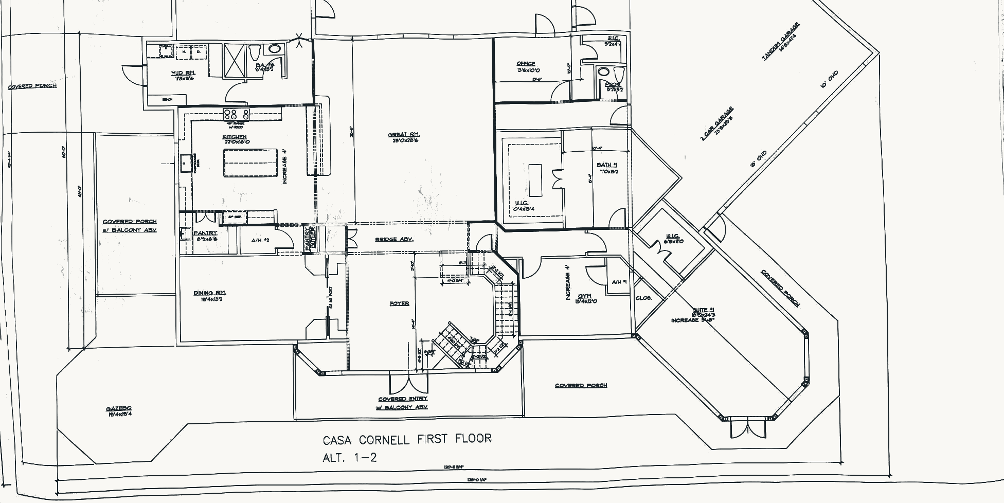
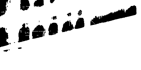
Two cleanup methods were run and compared. Black-hat morphology cleared the cast shadow but left paper wrinkle behind, so it was rejected. RGB consensus separated printed ink from the blue window light and from most of the paper texture, and that is what shipped.
File size agrees. The rejected black-hat PNG is 3,117,022 bytes against the selected consensus PNG at 349,719, about nine times the noise.
Shadow gone, wrinkle kept. Dirtier than the method it lost to.
Ink coverage 25.6% down to 7.3% on floor one, 22.8% to 7.7% on floor two.
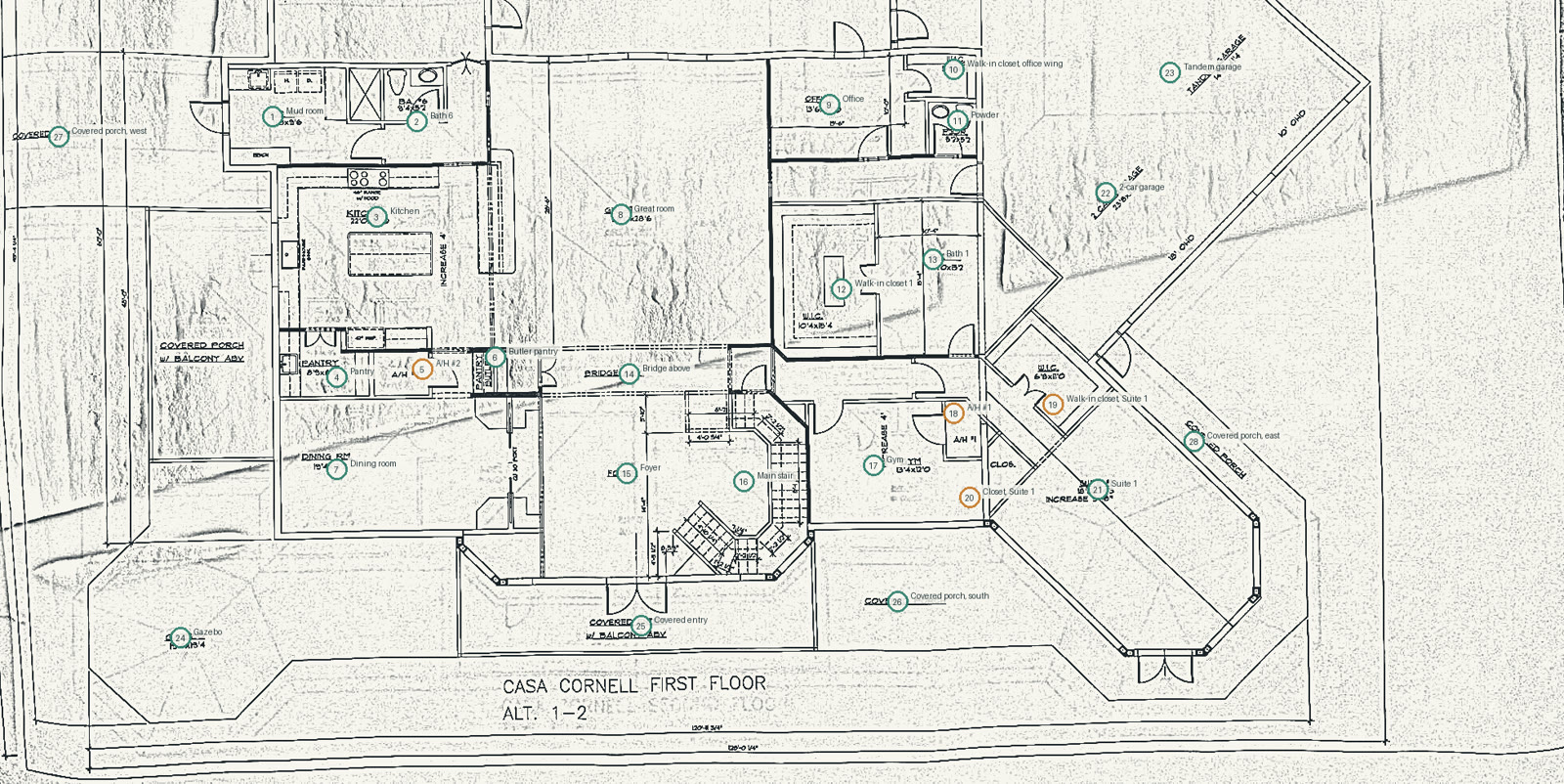
Every dropped pixel painted back onto the original, so the deletion can be checked.
Optical-density threshold sweep: at 0.14 the pass began attenuating low-contrast one-pixel dimension ticks and dashed construction lines, so 0.10 was selected. Neutral-ink boost was measured and then disabled at 0.0, because that path could only add ink, never take it back.
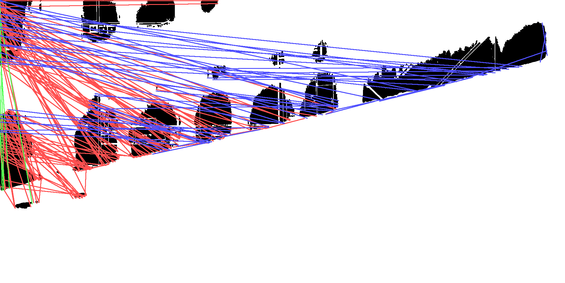
Classical computer vision on a photographed plan: flat-field correction to remove the window gradient, a Hough transform for lines, a max-pooled wall grid, a room classifier, then an SVG. Each stage worked on its own terms. The output was not this house.
They are kept because the rule the current pipeline runs on came from watching them fail: what a label says and what geometry claims are stored separately.
Illumination gradient removed. The one stage that worked, and the approach is still in use.
Finds every straight edge, including hatching, dimension ticks and the sheet border. Nothing tells it which ones are walls.
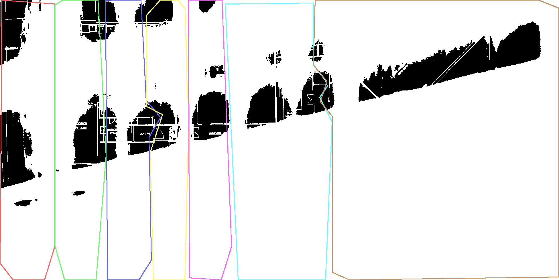
Max-pooling made the walls thick enough to connect and thick enough to swallow the door openings.
Rooms invented wherever the grid closed a loop. Several of them are in the wrong place.
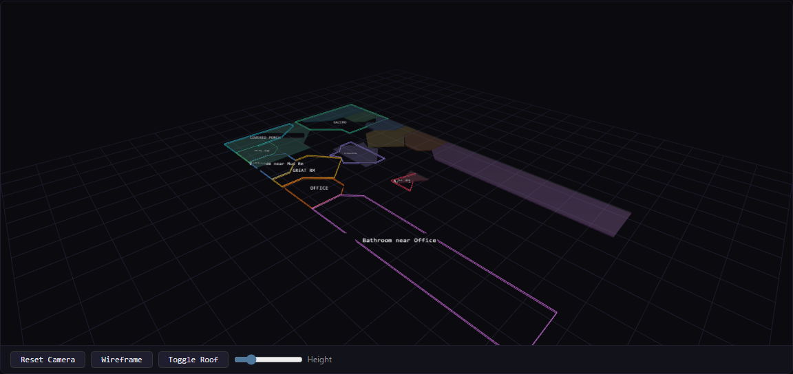
The wrong footprint, lifted into 3D. The same errors as the stage above, now in three dimensions.
Nothing downstream guesses. A room exists because a person read the label on the sheet and signed it off. A polygon exists only if its edges land on ink that survived cleanup. The two live in separate files, so the distinction sits in the data rather than in a caption.
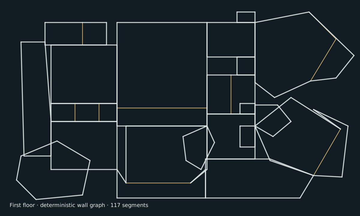
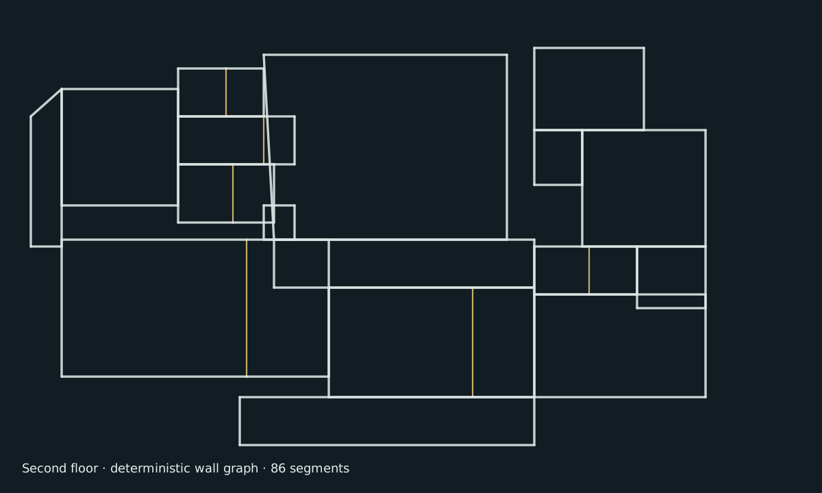
The reviewed schema carries 51 named spaces across 2 floors with 19 doors and openings. A separate room-perimeter graph carries 203 edges, 117 on the first floor and 86 on the second, the boundaries of the reviewed room polygons, each one naming the space or spaces it bounds.
It ships as wall-graph.json, and this page used to describe it as a wall graph. Its
own process manifest does not: it is kept there as rejected analysis evidence, “not rendered as
an architectural wall graph.” These edges are room boundaries. They carry no thickness and no
centerline, and a partition between two rooms appears once, flagged shared. The filename
is sealed and stays; the description does not.
Only 3 polygons were promoted to geometry. The rule is written into the file: a room in the label inventory does not become geometry by implication.
Drawn in the photograph's own pixel coordinates. Nothing was straightened to make them fit.
Every other draft polygon behaved like a bounding box or crossed a source wall under independent review. Those stayed analysis evidence and were never used.
Acceptance threshold: 75% of edge samples within uncertainty plus 2 px of preserved source linework. Kitchen and Great room overlap by 0 px². Shipped with this page: wall-graph.json, floor-01-wall-graph.svg, floor-02-wall-graph.svg, verified-schema.json, accepted-traces.json, accepted-traces-validation.json. Every figure above is counted from those files when the page is built, not typed in.
The full photo-to-geometry sequence as a standalone instrument, with its own camera and per-trace uncertainty readout. It is driven from this page rather than opened separately.
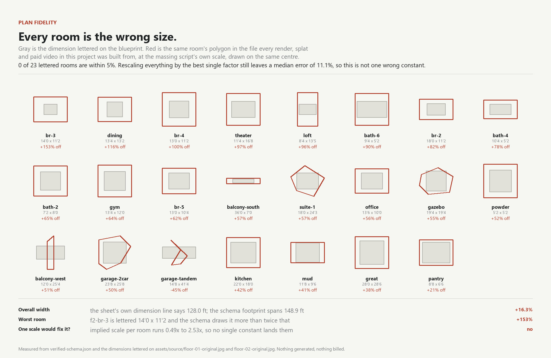
Everything after this point on the page is built on the file the section above produced. Today it was measured against the drawing it came from, for the first time. The blueprint carries its own answer key: the draftsman lettered almost every room with its size, and those strings live on the paper, so each one tests a polygon.
Each lettered dimension was read off the two source photographs and held against the minimum-area rectangle of that room’s polygon, converted through the massing script’s own scale constant. 0 of 23 rooms land within 5%. 23 are worse than 10%. The median room is out by 59.5%. The sheet’s own dimension line reads 128.0 ft across; the schema footprint spans 148.9.
Those 23 strings are the one hand-typed input in the whole check, so before anything was rebuilt on them all 23 were read again at 6–10× zoom off the same photographs. 3 had been typed wrong. KITCHEN letters 22’0″×16’0″ and had been entered 18’0″ deep; DINING RM letters 19’4″ wide and had been entered 13’4″; PANTRY letters 8’9″ and had been entered 8’8″. The other 20 stand, and every number on this page is the corrected run. The verdict held: 0 of 23 within 5% before the audit and after it.

One wrong scale constant would explain this, so that was tested first. The implied scale runs from 0.49× to 2.53× across rooms. Rescaling everything by the best single factor leaves a median absolute error of 11.9% and lands 12 of 46 room sides within 5%. Splitting by sheet gives the same picture: floor one spreads 0.69–1.90× and floor two 0.49–2.53×. Inside single rooms the two sides often disagree: in 11 of the 23 they imply scales more than 10% apart, and in 5 more than 25% apart. The west balcony comes out at 0.49× along one side and 1.19× along the other. A room with two different scales is the wrong shape, and a scale correction can only reach the wrong size.
This invalidates the metric claims this page makes about the building. The 47.9 m frontage below, the wall lengths in the opening schedule, the orbit radii fitted to those bounds, and the eight splats trained on frames of that geometry all describe a house that differs from the one on the paper. The method survives: registration rates, PSNR against held-out views, the chaining refutation, the alpha-semantics finding, the arbiter gate and the price evidence all compare runs against each other. The reconstruction pipeline worked. It was pointed at the wrong house.
Measuring this cost $0.00. The check now runs as a gate, so corrected geometry has something to pass.
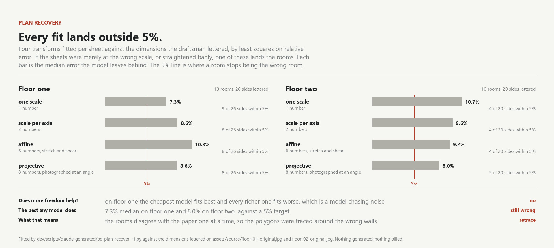
The measurement above says the rooms are wrong. It leaves open how expensive that is. If the two sheets were digitised at the wrong scale, or photographed at an angle and straightened badly, a few numbers per sheet put every room back where it belongs and nothing has to be drawn again. If the polygons were traced around the wrong walls, no transform of the page can move one room without dragging its neighbour along. Those two worlds cost a morning and a week.
Four models were fitted per sheet against the dimensions the draftsman lettered, by least squares on relative error, each measured with the same minimum-area rectangle the section above used: one scale, one scale per axis, affine, projective. Degrees of freedom run 1, 2, 6 and 8 in that order. A page that was merely photographed at an angle is exactly what the projective model describes, so if that is what happened, the last one lands the rooms.

On floor one the cheapest model fits best. One scale leaves a median of 7.3%; a scale per axis takes it to 8.6%, adding stretch and shear to 10.3%, and the projective fit comes back to 8.6%. Every model with more freedom than a single number fits worse than the single number, which is what a model chasing noise looks like: there is no consistent distortion in the sheet for it to find. Floor two improves with freedom and still stops at 8.0%. Across all eight fits the most sides any of them lands inside 5% is 9 of 26 on floor one and 5 of 20 on floor two.
So the rooms disagree with the paper one at a time. The plan has to be rebuilt from the lettered dimensions rather than repaired, and the lettering is the thing to rebuild it from, because it is the only part of the drawing that states a number instead of implying one. That is the next piece of work, and everything downstream of the schema waits on it: the massing, the four elevations, the opening schedule, the orbit radii and every splat trained on frames of that geometry.
Fitting all eight models cost $0.00. Finding this out before generating another elevation is the whole point of having measured it.