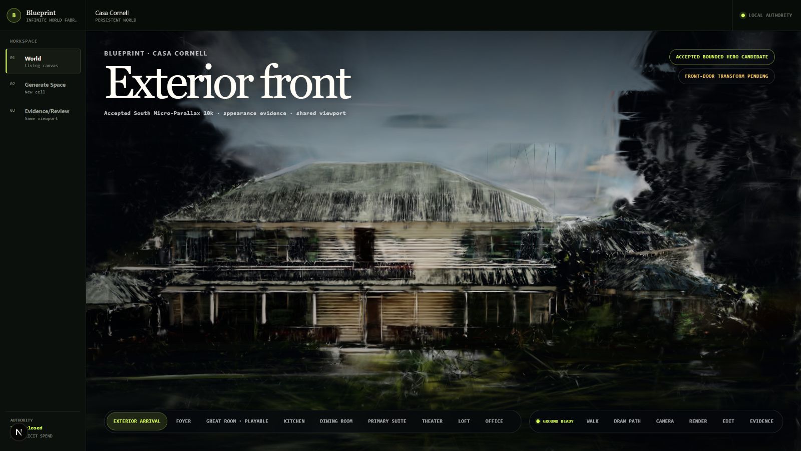
Casa Cornell
Preview build5 August 2026

Two photographs of a paper plan, turned into a house you can walk through.

This runs live in the page. Drag the bar or pick a step. Nothing here is a mock-up: the walls, rooms and dimensions are drawn from the same reviewed files the build itself reads.

Skip to the reconstruction you can move the camera in → four models, 104 solved frames

Photograph of the first floor plan
The same plan after deterministic cleanup
Scanning
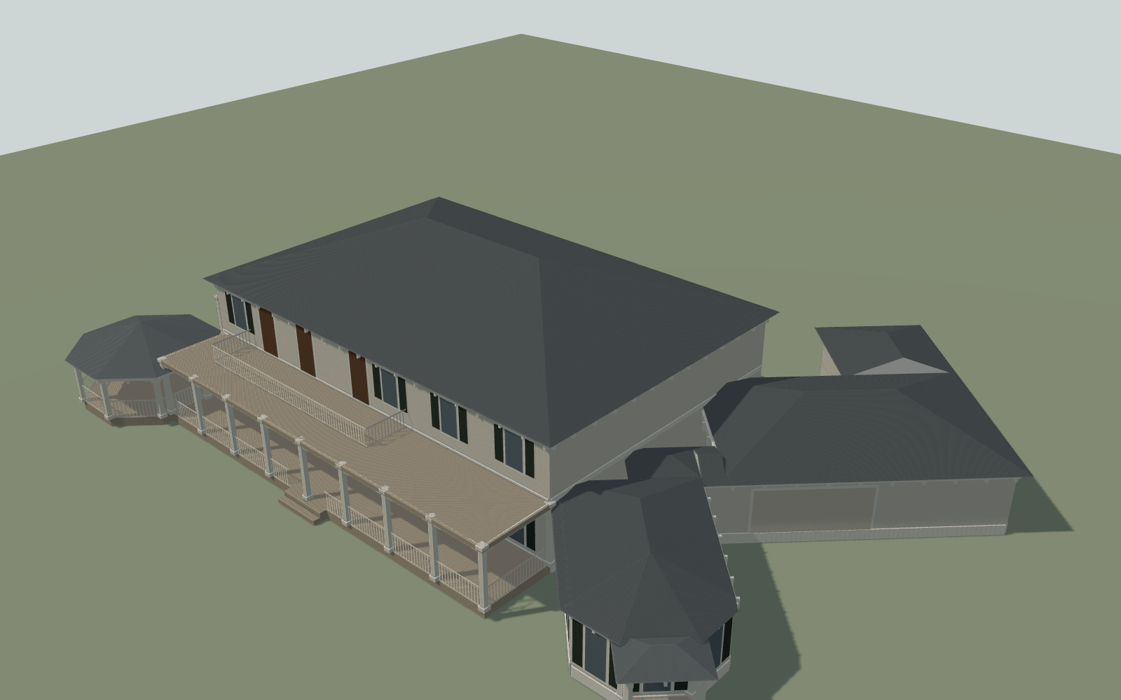
Generated exterior of the house
Source photographSamsung SM-F946U · 6 March 2026
01The input

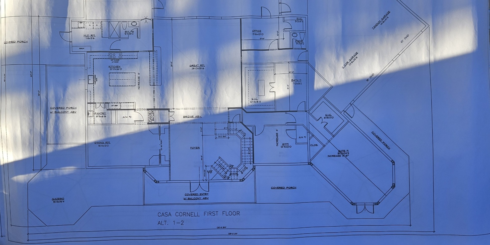
The whole input is two phone photographs of a sun-lit sheet.

Both carry Galaxy Z Fold5 EXIF dated 6 March 2026. There is no CAD file, no survey, no DWG. Everything downstream has to be recovered from paper that was photographed at an angle, under a window, with a shadow across one corner.

First floor plan as photographed
Source1952 × 978

First floor

28 named spaces. Blue cast from the window, cast shadow at the lower left.

Second floor plan as photographed
Source1883 × 1018

Second floor

23 named spaces. Sharper sheet, heavier paper wrinkle through the middle.

01bCleanup

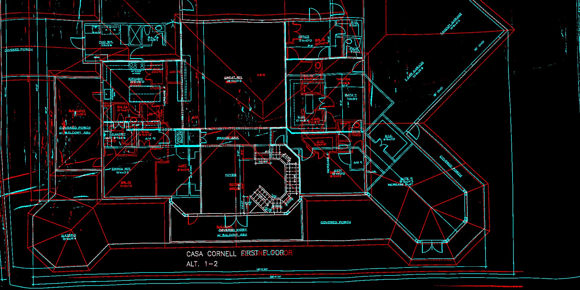
Take out the paper, keep every mark that could be evidence.

Cleanup ran as a bake-off, and the option that looked most aggressive lost. Black-hat cleared the broad cast shadow but let too much neutral wrinkle texture through, so it was rejected as the final line source. RGB consensus separated black printed ink from blue illumination and most of the paper relief, and that is what shipped.

The file sizes say the same thing. The rejected black-hat PNG is 3,117,022 bytes against the selected consensus PNG at 349,719. Roughly nine times the noise.

Black-hat cleanup result
Rejected

Black-hat morphology

Shadow gone, wrinkle kept. Rejected for being dirtier, not cleaner.

RGB consensus cleanup result
Selected

RGB consensus

Ink coverage 25.6% down to 7.3% on floor one, 22.8% to 7.7% on floor two.

Evidence overlay audit
Audit

What got removed

Every dropped pixel drawn back over the original, so the deletion is reviewable instead of trusted.

Optical-density threshold sweep: at 0.14 the pass began attenuating low-contrast one-pixel dimension ticks and dashed construction lines, so 0.10 was selected. Neutral-ink boost was measured and then disabled at 0.0, because that path could only add ink, never take it back.

02The first tries

Classical vision was taken as far as it goes, and where it broke set the rule the pipeline still runs on.

Straight classical vision on a photographed plan. Flat-field correction to kill the window gradient, Hough transform for lines, max-pooled wall grid, a room classifier, then an SVG. Each stage was reasonable. The result was not the house.

These are kept because they are the reason the current pipeline separates what a label says from what geometry claims. That rule came out of watching this fail.

Flat-field corrected plan
Stage 3

Flat-field

Illumination gradient removed. This part actually worked and survives in spirit today.

Hough line detection output
Rejected

Hough lines

Finds every straight edge including hatching, dimension ticks and the sheet border. No idea which ones are walls.

Max-pooled wall grid
Rejected

Wall grid

Max-pooling made the walls thick enough to connect and thick enough to swallow the door openings.

Automatic room segmentation
Rejected

Auto room split

Rooms invented where the grid closed a loop. Confident, coloured, and wrong in several places.

Early 3D extrusion
Rejected

First extrusion

The wrong footprint, lifted into 3D. Extruding a bad plan gets you a bad plan you can orbit.

What changed

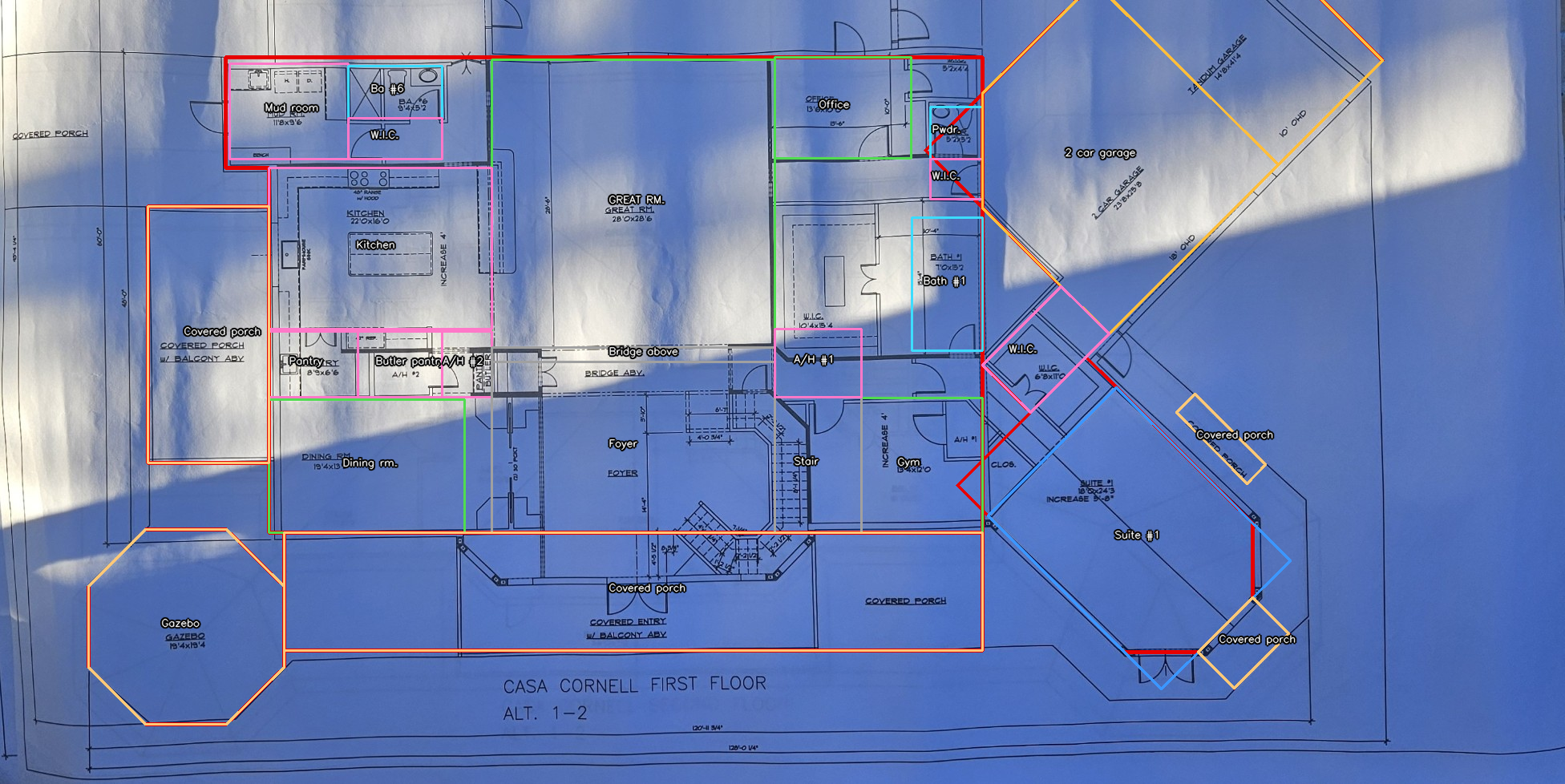
Nothing downstream is allowed to guess any more. A room exists because a person read the label on the sheet and signed off on it. A polygon exists only if its edges land on ink that survived cleanup. The two are stored separately, and the difference is written into the files rather than into a caption.

03Authority

A label is not geometry, and the difference is written into the files.

The reviewed schema carries 51 named spaces across 2 floors with 19 doors and openings. A separate wall graph carries 203 segments, 117 on the first floor and 86 on the second.

Only 3 polygons were ever promoted to geometry. The rule is written in the file itself: the label inventory is not promoted to geometry by implication.

First floor plan with the two accepted traces drawn on it
PromotedSource pixel space

Kitchen and Great room

Drawn in the photograph's own pixel coordinates, which is what source-aligned means here. Nothing was straightened to make them fit.

Second floor plan with the accepted theater trace drawn on it
PromotedSource pixel space

Theater

Every other draft polygon behaved like a bounding box or crossed a source wall under independent review. Those stayed analysis evidence and were never used.

Acceptance threshold: 75% of edge samples within uncertainty plus 2 px of preserved source linework. Kitchen and Great room overlap by 0 px². Shipped with this page: wall-graph.json, floor-01-wall-graph.svg, floor-02-wall-graph.svg, verified-schema.json, accepted-traces.json, accepted-traces-validation.json. Every figure above is counted from those files when the page is built, not typed in.

03bThe same sequence, higher resolution

The full photo-to-geometry sequence as a standalone instrument, with its own camera and per-trace uncertainty readout. It is driven from this page rather than opened separately.

04The first picture

The house has not been built, so the first picture of it had to be generated too.

There is no photograph of this building anywhere in this project and there cannot be one. It exists as two sheets of paper. The traced plan gives walls, and walls give massing, but massing is not a house — no siding, no brick, no roof pitch, no light in the windows. So the plan and a written style specification were handed to an image model, and the front elevation below is what came back.

Everything further down this page descends from that one image: every video clip, every solved frame, every reconstruction. It inherits whatever the elevation got right, and whatever it got wrong.

The generated front elevation: a two-storey
    cream lap-sided house with a brick bay tower on the right, a glazed sun-room wing on the left, hipped
    standing-seam metal roofs, warm light in the windows, wet brick walk and driveway, live oaks and
    palms around it.
The seed elevation, and the only view of this house that has ever been made from the plan. No camera EXIF; an AIGC chunk in the source PNG and a generator C2PA manifest beside it. The bundle carries that provenance so the claim is checkable rather than asserted.

What the model was told it could not change, written down before any frame was generated: 2 storeys, 4 porch columns, 3 balcony bays, a five-sided brick bay tower on the right and a single-storey glazed sun-room on the left. The building is deliberately not left-right symmetric, and that asymmetry is the only thing separating a frame from its own mirror image. Every later frame is checked against that list.

04bThe gap

One elevation is not four, and that is why coverage stops where it does.

The plan calls for front, sides and back before any camera moves. Only the front exists. Four video clips were generated from it and fused into one reconstruction, and all four begin at the same anchor frame — so the entire solved dataset, 104 frames of it, stands within about 60° of the front door. Section 07 measures that ceiling four different ways and finds it saturating: a tenfold increase in camera arc bought 20° of extra readable view. That is not the reconstruction failing. That is the reconstruction correctly refusing to invent three elevations it was never given.

04cHalted

The first run at the missing angles asked for them ten degrees at a time, and the endpoint does not have degrees.

The plan for the other elevations was hierarchical: establish the whole orbit coarsely, then refine it. It was priced at $5.29, authorised, and stopped after $0.44 on its own pre-registered kill gate. The opening probe asked an angle-controlled image endpoint for 0°, 10° and 20° and got the same picture three times. At 30° it crossed an internal bucket boundary and returned a different house — different light, different massing, different roof. A second model from a different family behaved the same way.

Six generated frames in two rows.
    The top row, labelled zero degrees, zero degrees again and twenty degrees, is the same wet-driveway
    front view of the house three times. Bottom left, labelled thirty degrees, is a visibly different
    building in flat daylight with a garage and no wet driveway. The remaining two frames repeat the test
    on a second model at zero and ten degrees and return the same picture twice.
Azimuth is a step function, not a slope. 0° and 20° agree to cosine 0.9950, while re-requesting the same prompt twice agrees to 0.9984 — so the twenty-degree turn is indistinguishable from noise. 30° drops to 0.7947 and takes the building with it. Sealed as hierarchical-blueprint-20260810-r1 with the verdict withheld rather than failed: the orbit was never generated, so the hierarchy it was meant to test is untested, not disproved.

The correction is to stop asking for angles in words. A camera moving continuously inside a single video clip never names an angle at all. That is what the next round runs: one wide pass the whole way around the building with the elevation drifting as it goes, held together by the subject being small enough in frame to stay consistent, then successive passes that zoom into segments of the pass before them, each conditioned on the one it came from, until every face is covered at full detail. Sections 05 to 08 are the constraints that plan has to survive.

05Bake-off

Seven video models, one starting frame, and the screening picked the wrong winner.

All seven were driven from the identical generated still with the same prompt and negative prompt, then screened by a local proxy: feature continuity, camera motion, source retention, cut safety. Thirteen runs across two scenes, $8.44 actual against a $9.00 budget.

The proxy ranked Veo first at 90.9 and Kling fifth at 85.3. Kling is the one that actually reconstructed. That is why the screening file says in its own limitations that the ranking is triage only and must not be presented as a reconstruction result.

Screening formula: 35% feature continuity, 25% camera motion, 25% source retention, 15% cut safety, over SIFT correspondences with RANSAC fundamental geometry. It never ran a structure-from-motion solve, so it could not see whether the generated 3D was right. Persistent 2D texture matches features even when the geometry underneath is wrong, which is exactly how Veo won a race it then lost.

06The gate

Generate the video, then force it through the same solve as real footage.

Every clip gets fed to a structure-from-motion solve under pinned intrinsics. If the cameras cannot be recovered from the frames, the clip is rejected no matter how it looks. The scoreboard is how many of 210 image pairs come back geometrically calibrated.

The strongest number on the board belongs to a clip that was thrown away, and the cheapest win belongs to a clip that was never generated.

Camera guides · solved free, before any paid generation
Superseded

t025 · dolly parallax

gate
124 / 210
family
r6

The first guide that produced a solvable generation at all.

Selected arc

a100 · 1.00u truck, 18° sweep

gate
189 / 210
points
8,275

The middle arc of the r7 family, and the one that shipped.

Rejected on looks

a150 · 1.50u truck, 26° sweep

gate
198 / 210
solve
21/21 · 7,714 pts · 0.847 px
why out
roofline bend, foliage smear, 5 watermark pairs

Gated higher than the arc that shipped. Rejected anyway.

Best parallax

l100 · lateral dolly 1.00u

guide gate
190 / 210
clip gate
206 / 210
points
8,060 · 0.765 px

The best gate score in the project, guide and generated clip both.

Hard fail

pb100 · pure pull-back

two-arm solve
no sparse model
fallback
8 / 21 · 122 pts
saved
$0.50625

Radial-only parallax the mapper cannot bootstrap. Caught before spending anything.

The point of a free gate

Six candidates were rendered and solved locally at no cost. Five passed at 21/21 registered, 0.73 to 0.82 px, zero watermark-configuration pairs. One failed outright. Only the survivors were allowed to become paid generations.

candidates
6
passed
5
paid on failures
$0.00
Generations · in the order they happened
Rejected

R2

gate
210 / 210 fail

Looked fine. Solved as a single degenerate configuration on every pair.

First pass

R3

gate
132 / 210
points
8,576

The first generated clip that reconstructed at all.

Arc baseline

R4

gate
184 / 210
points
10,480
holdout
27.78 dB

Sharpest single arc. Narrow envelope: step off the path and it falls apart.

Current frontier

Orbit hop 1

joint solve
128 / 128
coverage
35.4° → 53.7°
calibrated
204 / 210

The strongest parallax signature in the project, and the first look past the corner.

06bHoldout PSNR

The bar to beat is the best clip we ever generated, not a camera.

There is no photograph of this house as built anywhere in the project. The baseline is the strongest prior generated clip, Kling 3.0 Pro image-to-video at $0.56, re-derived from scratch and reconstructing at 30.34 dB.

The donor repo had claimed 32.45 dB on the same data. That did not survive re-derivation and is recorded as unverified. The honest claim is the one that holds: generated video now reconstructs within 2.56 dB of the best prior generated clip, on a gate that rejected earlier attempts outright.

07Live reconstruction

The house was rebuilt from generated video. Load a model and move the camera yourself.

These are the trained Gaussian splats themselves, not renders of them. The camera orbits the house, so you cannot get lost — and it stops at the edge of the arc the solved frames actually cover. Four models are here so the differences are yours to check rather than mine to describe: the re-derived donor clip that set the bar, the first clip generated to a camera guide of our own, four clips fused into one model, and the orbit hop that pushed coverage past the corner of the house.

Nothing below this point is a picture standing in for a room. Every number attached to these models was measured on views the training never saw.

Step 1 — pick a model

Step 2 — load it

Drag to orbit, scroll to zoom, shift-drag to pan, R to reset. The viewer has preset viewpoints and a reset button of its own. Picking a different model above reloads it in place.

The orbit limit has been set four times, and only the fourth one looked at the frames.

A number picked out of the air gave a −55° preset of pure smear. A sharpness metric said three of the four models hold out to ±80°; at +80° there is no building in the frame at all. A collapsing splat does not go soft — the gaussians stretch into long streaks and the foliage shatters into confetti, and both of those raise sharpness, so the metric scored the collapse as healthy. It overstated every model and understated none, which is what measuring the failure mode instead of the subject looks like. Solved camera positions replaced it and are honest, but they answer a different question — where a solved frame stands, not how far the solve carries — and they are symmetric by construction when this property is not.

So the limit was set by looking. 52 frames were rendered through this viewer with the panel hidden, four models across thirteen azimuths at 10° steps, and each was marked clear, degraded or gone. The marks are recorded per frame, so any one of them can be argued with by pointing at the frame.

A contact sheet of 52 rendered frames: four reconstructions down the side, thirteen azimuths from minus 60 to plus 60 degrees across the top, each frame carrying a coloured rail marked clear, degraded or gone. The middle of every row is the house; both ends are coloured streaks.
The evidence, at the size it was judged at — scroll it sideways. Reading along any row, the house survives a run of frames in the middle and then stops being a house — earlier on the left, because turning left runs into a foreground oak and palm that no clip ever resolved, while turning right opens onto the driveway the generated clips covered. Every model gives out further right than left, so any symmetric limit is wrong twice.
Four reconstructions on one azimuth ruler. For each, small ticks mark the solved camera positions, a filled block marks the arc that still reads as the house, and an outline marks how far the viewer lets the camera go.
Three different spans, drawn separately because collapsing them into one number is what went wrong the first three times. The viewer clamps to the outline, sends its edge presets to the filled block, and leaves the ticks alone. kling-rederive-30k was previously clamped to the 5.9° its cameras span; it now opens across 30°.

Readable arc saturates, which is a problem for the plan to generate our way around the property.

Line the four models up by how much camera arc each solve was given and the return collapses monotonically: 5.06× readable degrees per camera degree, then 1.75×, then 1.01×, then 0.83×. A 10× spread in capture width bought 20° of extra readable view, and the two widest captures read no wider than the arcs their own cameras stand on. Adding generated frames further round the house is buying arc on the wrong side of that knee — the next gain has to come from making the pixels we already have count for more, not from standing in more places.

Readable arc plotted against camera arc for four reconstructions, with the one-to-one line drawn. The points rise from 30 degrees readable at 6 degrees of camera to 50 degrees readable at 60 degrees, crossing from far above the line to below it.
Above the dashed line a solve returns more readable view than it was given camera to work with. Below it, the capture is wider than the result it bought. Numbers read live from splat-arc-bands.json, generated from the sealed viewer-arc-20260811-r2 manifest; the instrument it replaced is sealed too, at full size, because its frames are what refute it.

Making the pixels count for more meant telling the trainer “I don’t know”. It turns out we can’t.

Feeding generated frames into a reconstruction costs −1.43 dB against a baseline built from solved frames alone, measured on held-out views. We also know why: a warped frame is two things stitched together — pixels resampled from a solved frame, and pixels a model invented where nothing was visible — and the warp knows which is which, per pixel. So the obvious repair is to hand the trainer the resampled half and mark the rest unknown.

That repair has one load-bearing premise: that unknown is a thing the trainer can be told. The only candidate is a transparent input pixel, and the manual sentence for it reads either way. Three instruments on this project have already measured something real and had the answer used for a question it wasn’t answering, so this one got tested instead of assumed — a rectangle punched to transparent in half the training views, the other half left intact, both arms otherwise identical.

Three crops of the same balcony:
    the source frame, the model trained on intact images, and the model where half the training views had a
    rectangle punched to transparent. Inside the outlined rectangle the third crop is pulled dark — the lit
    window dims and the white rail greys — while everything outside it matches.
Transparent does not mean no opinion. It means nothing is here, and the trainer believes it: inside the box the held-out frames come back 5.53 dB worse, while outside it the two arms agree to 0.11 dB — the noise floor. The damage stops exactly at the edge of the box, which is what makes it the mask and not a bad rerun. Turning the alpha loss weight to zero does not switch it off.

This is strictly worse than feeding the invented pixel through. A wrong colour is one bad observation competing with good ones; a wrong emptiness deletes geometry that other views got right. Masking a warped frame down to its honest pixels would carve the disoccluded regions out of the house. Two short training runs and one rectangle cost about four minutes and stopped a full experiment that would have come back negative and been written up as confidence weighting doesn’t help — which would have been false. Sealed as refuted in alpha-semantics-20260811-r1; the same idea still has a coarser form left, selecting whole frames by how much of them was invented.

08Falsified

Walking the camera past the solved frames in small steps is worse than jumping, and the threshold that says so was written first.

The idea was sound on its face. Reproject a solved frame a few degrees using its own depth, fill the sliver that opens behind the objects, repeat. Each step invents almost nothing, so a chain of them should walk a long way and stay mostly real. Eight chains were run at step sizes from 0.5° to a single 30° jump.

Every one of the six preregistered step sizes failed. Reaching 30° in ten steps leaves 27.0% of the frame traceable to the source frame. Reaching the same 30° in one jump leaves 66.5%. Small steps do invent less each time — and they invent it on top of what the last step invented.

The source frame: the house, sharp, from the solved camera
Where every chain starts

The solved frame

invented
0.0%
camera
r4_0031, solved

One frame of the fused solve. Nothing in it was warped, filled or guessed.

After a single 30 degree warp the house is still legible under heavy speckle
One jump

30° in a single warp

invented
33.5%
largest hole
16.2% in one piece
steps
1

Two thirds of it is still the source frame, and it still reads as the building.

After ten three-degree warps the house has smeared away entirely
Ten steps to the same place

30° in ten 3° warps

invented
73.0%
largest hole
1.1%
steps
10

Every individual step opened only 7% of the frame. There is no house left.

The obvious suspect was depth drifting as it is carried forward, so the 3° chain was run again with depth re-rendered from the splat at every step — a perfect oracle the real pipeline can afford. It moves the result from 27.0% to 33.4% and the frame is just as gone. The failure is not depth. It is that the same 7% hole opens every step and lands on ground the previous step already invented.

Nine chains plotted as source-derived pixel fraction against cumulative azimuth. All eight multi-step chains fall below the 50 percent threshold before 30 degrees; the single 30 degree jump ends at 67 percent.
Every line reaches the same 30° of azimuth. The dashed line is the falsifier, fixed before the first warp ran: more than half the frame invented at every registered step size. The one line that finishes well above it took a single step. The dimmed dashed chain is the depth-oracle arm, which was run afterwards and does not vote.
08bWhat replaces it

If chaining is out, every pose is one direct warp — so the question becomes how far one reaches, and which way it should turn.

Two things decide that, and they are not the same thing. How much of the frame has to be invented is the labour. How big the largest single hole is decides whether a generative model gets one bounded region it can see the shape of, or a scatter of speckle it cannot. On r4_0031, at the far positive end of the arc, turning one way costs of the frame and turning the other costs — a gap of points, which invites the tidy explanation that the occluders sit to one side of the house. Two more frames were measured and they do not support it: the cheaper direction is not the same direction for all three. It is a property of the frame, so it has to be measured per warp rather than assumed. Sliding the camera to the same place without rotating — the control — is worse than either, everywhere, on every frame, because rotation keeps the subject in the picture and translation slides it out.

Six panels: three source frames across, invented pixel fraction on the top row and largest single hole on the bottom, each plotted against azimuth out to 30 degrees. In every panel the dolly control is worst. On r4_0031 the outward orbit costs 33 percent against the inward 25; on l100_0023 the two directions nearly coincide at 32 and 33 percent; on r4_0012, inside the arc, they are 30 and 26.
One warp, no chain, out to the 30° the chains were trying to reach. The accented line is the direction that leaves the solved arc — the only direction that buys new coverage — and on the frame where turning is cheapest, the cheap direction is the useless one: it points back into azimuth the solved frames already cover. Extending coverage means paying the higher number. And the two costs disagree about which direction to prefer: the cheaper-to-invent direction on r4_0031 scatters what it opens across separate holes against for the expensive one, so it is better for labour and worse for handing a generative model one region to fill.

The number under all of this: the solved frames cover of azimuth, , and that is the entire capture. A full orbit of the property is 360°. Chaining was the mechanism that was supposed to cross that gap and it does not work, so every pose has to be one direct warp from a solved frame — and how far one of those actually reaches is a question this curve could not answer, because it stopped at 30° and because the measurement under it was wrong. 08c corrects it. Everything past the reach it establishes has no solved frame to be warped from at any distance, which is not an inpainting problem — it is the generation problem branch A was opened on, and the arbiter has already measured what generated frames do to a reconstruction.

What this does not say: the warp itself is sound — pixels outside the hole survive every inpaint bit-identical, asserted at every step, and the run reproduces byte-for-byte. It does not say a better inpainter would look worse; it says a better inpainter would be inventing the same fraction of the frame, and the fraction is what was being measured. No reconstruction was trained on these frames. Costs $0.00: everything here ran locally. Numbers read live from dwi-chains.json and dwi-reach.json.

08cCorrection

The warp had no idea which way a surface was facing, so it kept re-supplying the front of the house to cameras standing behind it — and every percentage above was measured that way.

The curve gave itself away before anything else did. On r4_0031 a 120° orbit scored points cheaper than a 90° one. Cost cannot fall as the camera moves further from the only view ever captured of the subject, so the measurement was supplying pixels it had no right to. It was: a front-only capture has no back of the house in its depth map, so nothing occludes the facade when it is reprojected into a camera on the far side. The facade arrives again, inverted and see-through, and the metric counts it as real. Three other explanations were tested first and all three failed — sky counted as supplied (it is 0.0% of every frame), depth noise (median-filtering the source makes it slightly worse), and sampling cracks (a fatter splat closes them by smearing the house away). The fix is one test: a source pixel may only supply a destination pixel if its surface still faces the destination camera.

Thirty degrees of orbit, measured without the facing test: the house under heavy speckle
As r2 measured it

30°, no facing test

invented
this is the frame
the page called two-thirds real

Backfacing material is being supplied here, and nothing in the metric objects to it.

The same thirty degree orbit with the facing test on: visually almost identical, with slightly more of the frame left empty
Corrected

30°, facing test on

invented
looks like
the frame on the left

This is why it survived a round. At 30° the defect is not visible — it is a few points of cost.

The corrected thirty degree frame with every pixel the facing test withdrew painted in rust red. The withdrawn set follows the right-hand wing of the house and the roof edge; the porch face, still pointed at the camera, comes through untouched
The difference between those two frames, painted on the one that survives: every pixel in rust is material the uncorrected warp supplied and the facing test withdrew — of the frame. It is not erosion. It follows the wing turning away from the camera and the roof edge, while the porch face, still pointed at the camera, comes through untouched. The densest patch is foliage rather than building ( rejected inside the worst 30% window), which is the honest caveat: leaves have no stable normal, so some of that rejection is noise. The structure on the house is not.
A hundred and eighty degrees of orbit, no facing test: the camera stands behind the house and is shown the front facade through the walls
The tell

180°, no facing test

invented
what you are seeing
the facade, through the walls

The camera is behind the house. This scores cheaper than the 90° view of the same building.

The same hundred and eighty degree orbit with the facing test on: almost the whole frame is empty, because a front-only capture knows nothing about the back of the house
Corrected

180°, facing test on

invented
honest answer
there is no back of the house

What a front-only capture actually knows about the far side, which is almost nothing.

Invented pixel fraction against orbit angle out to 180 degrees for two source frames. The dashed uncorrected curve rises, turns back down past 90 degrees and on r4_0031 never crosses half the frame invented. The solid corrected curve rises throughout and crosses at 57 and 44 degrees.
The same two frames, out to a half turn instead of 30°. The dashed line is what was sealed: it turns back down, and on r4_0031 it never reaches half the frame invented at all — not even at 180°, where the camera is behind the building. The solid line is the same warp with the facing test on. Across all four measured arms, are now monotone against before. The correction is a lower bound, not an exact figure: normals taken from splat-rendered depth are noisy, so the test over-rejects slightly at small angles and under-rejects at large ones.

Which raises the obvious question about everything above this section, so it was re-measured rather than argued: does the chaining verdict survive its own correction? Both decisive arms were run again with the facing test on. One 30° warp keeps of the frame traceable to the source frame, against before. Ten 3° warps to the same place keep , against . Every number in 08 and 08b moves down — and the gap between them widens, from to points. The correction makes the falsification stronger. The plate figures above still read as they were sealed, which is why they are labelled as measured rather than quietly restated.

Plan view of a full orbit of the property. Forty degrees is solved, a hundred and one more degrees are reachable by one outward warp from each end frame, and the remaining two hundred and eighteen degrees have no solved frame that can reach them at any angle.
The planning number this branch exists to produce. Chaining loses, so a warp can only start from a solved frame: the reachable band is the solved arc plus one outward reach at each end — past r4_0031 and past l100_0023, at half the frame invented. That is of azimuth. The remaining of a full turn around the property — has no source frame at any angle. No improvement to the warp changes it. It is a statement about where the camera was.

What this does not say: it does not say the reach numbers are precise. Invented-pixel fraction is a labour estimate, not a usability bar, and the section above already showed it moving ten points on a free parameter of its own measurement. It says something narrower and harder to argue with — 60% of the orbit has nothing to warp from, and that is the part no better inpainter, warper or threshold touches. Costs $0.00: everything here ran locally against the sealed r2 geometry, read-only. Numbers read live from dwi-far-reach.json, generated from the sealed r3 manifest; the four plates above carry their payload hashes in dwi-facing-plates.json.

09Standing rooms

Before the reconstruction worked, each room was a plate. These are kept as lineage, not as the product.

Eight schema rooms and the exterior shell, each carrying the dimension string and review confidence straight off the reviewed plan, so what you are looking at and what the file says stay attached to each other. That link is the part worth keeping.

The images themselves are presentation plates, not measured space. They are useful for finding a room and checking its label against the plan, and they are the reason the work moved to real reconstruction: a plate cannot be walked around, and the section above can.

01 / 09

Exterior

Select a world  ·  ← →
A

Same house, four treatments

The Victorian pass is the clearest case of looks and geometry disagreeing. It is the best-looking exterior in the project and it was rejected, because the restyle moved the roofline and the reconstruction could not solve it.

10Automated tour

One take, ninety-six seconds, every control moving under script.

Nothing here is cut together. A single recording drives the room change, fireplace intensity and flicker, window spill, the day to night slider, the counter practicals, an audio-reactive party mix, rain with two lightning strikes, then the exterior with a heading pan and a horizon lift.

Jump to any beat below. The values shown are the ones the script actually sends.

0:00 / 1:35 No audio track. The audio-reactive drive shows in the lighting.

Lighting took three passes. At practical intensity 3.6 with room wash 2.2 the party's audio-reactive drive clipped the whole room to white-cyan for about six seconds. Dropping to saturation 0.7 and wash 1.6 stopped the clipping and washed everything pastel. The shipped values are saturation 0.9, practicals 2.6, wash 1.2, party mix 0.9. High saturation carries the colour while low intensity keeps the headroom.

11Where it stands

Wider coverage cost 1.34 dB, and one view still fails.

Fusing the R4 arc with three new clips put 104 of 104 images into a single model on the first try. 33,572 points at 0.889 px. Lateral camera coverage went from 6.5 to about 13.8 units.

It costs 1.34 dB on the R4 arc for roughly three times the view volume, and R4's worst endpoint got 1.19 dB better, because every new clip observes that region.

Fixed

Pull-back driveway

before
fogged by veiling sheets
after
house and wet driveway crisp
obstruction
50.4% → 41.1%

The walk-up view a person actually uses.

Improved

Yaw extremes

left
neon blobs → real foliage
right
more real palm detail
top-100 share
15.4% / 13.4%

Both edges gained real edge content instead of invention.

Still failing

25° low-eye pitch-down

top-100
71.9% of view weight
scale ratio
256× scene median
anisotropy
2,543

Not a floater problem. No capture yet sees the near ground at a grazing angle.

Next

What that needs

A clip whose camera is low and pitched down while translating, so a driveway approach dolly at −20 to −25°. That is a new control family and a paid decision, so it is not in this build.

full 360 estimate
~18 hops · $11–14

Also on the record, because leaving it out would be dishonest. One r5 clip completed and billed at $0.50625 with 175.6 s of inference, then the result store returned HTTP 500 on all 23 retrieval attempts over 24 minutes. It was excluded from the fusion rather than worked around. Request 019fd250-e52d-7713-b0f1-63e242925bc2 is still retryable if that store recovers.

Sealed runs
 

Each one is a manifest with a per-file sha256 index, an authority boundary and a spend record.

Reviewed spaces
51

Across two floors, 33 of them carrying a legible dimension string off the sheet.

Wall segments
203

Counted from the shipped wall graph, 117 plus 86, rather than asserted in prose.